

Black Widow: Difference between revisions
No edit summary Tag: Manual revert |
No edit summary |
||
| (5 intermediate revisions by the same user not shown) | |||
| Line 5: | Line 5: | ||
|weight = 11 lbs. 9 oz. (5.2 kg) | |weight = 11 lbs. 9 oz. (5.2 kg) | ||
|motor-size = 54mm | |motor-size = 54mm | ||
|flights = | |flights = 6 | ||
|max-altitude = 13570 feet AGL (TeleGPS) (4136 m) | |max-altitude = 13570 feet AGL (TeleGPS) (4136 m) | ||
|max-speed = 1325 ft/sec (903 mph, Mach 1.18) (Raven, accelerometer) | |max-speed = 1325 ft/sec (903 mph, Mach 1.18) (Raven, accelerometer) | ||
|status = | |status = Ready to fly | ||
|simfile = https://github.com/DanCrank/openrocket-sim-files/blob/master/BlackWidow.ork | |simfile = https://github.com/DanCrank/openrocket-sim-files/blob/master/BlackWidow.ork | ||
}} | }} | ||
Black Widow is a rocket I built in late 2015 / early 2016 to replace [[Home Alone]] after [[2015 Launch Reports#Home Alone, L990|its crash in Elsberry]]. The kit is a Rocketry Warehouse (now Composite Warehouse) Dominator 3, no longer in production. It's very similar in size to Home Alone, but with a different fin shape featuring a curved trailing edge. The kit came with a very nice looking red-anodized nose cone tip and tailcone motor retainer, so I finished it in a black and red color scheme. | Black Widow is a rocket I built in late 2015 / early 2016 to replace [[Home Alone]] after [[2015 Launch Reports#Home Alone, L990|its crash in Elsberry]]. The kit is a Rocketry Warehouse (now Composite Warehouse) Dominator 3, no longer in production. It's very similar in size to Home Alone, but with a different fin shape featuring a curved trailing edge. The kit came with a very nice looking red-anodized nose cone tip and tailcone motor retainer, so I finished it in a black and red color scheme. | ||
I [[Black Widow (altimeter bay redesign)|redesigned Black Widow's altimeter bay]] in 2023. | |||
<gallery mode="slideshow"> | <gallery mode="slideshow"> | ||
| Line 31: | Line 33: | ||
[[2016 Launch Reports#Black Widow, K650|SLRA Fall 2016, K650]] | [[2016 Launch Reports#Black Widow, K650|SLRA Fall 2016, K650]] | ||
[[2023 Launch Reports#Black Widow flight #6, L1000|NSL East 2023, L1000]] | |||
== Checklist == | == Checklist == | ||
Pre-launch (before leaving town): | Pre-launch (before leaving town): | ||
* Clean everything! | * Clean everything! | ||
* Charge batteries: TeleGPS, TeleBT, | * Charge batteries: Raven LiPo, TeleGPS, TeleBT, old Mobius, pad camera, antenna camera, drill | ||
* Clear memory in | * Clear memory in old Mobius, pad camera, antenna camera | ||
* Check TeleGPS config and reset / clear memory | * Check TeleGPS config and reset / clear memory | ||
* Check Mobius config (correct video mode; sync clock), test and clear memory | * Check Mobius config (correct video mode; sync clock), test and clear memory | ||
* Test TeleGPS/TeleBT and leave transmitter battery unplugged | * Test TeleGPS/TeleBT and leave transmitter battery unplugged | ||
* | * Connect Raven battery (connect the two-pin plugs on the sled with pull-pin removed); check Raven config (set main pyro altitude to 900 feet); disconnect Raven battery | ||
* Check contents of recovery pack | * Check contents of recovery pack | ||
| Line 51: | Line 53: | ||
* Assemble ejection charges (1.5g Goex + wadding) x4 | * Assemble ejection charges (1.5g Goex + wadding) x4 | ||
* Refold / repack parachute and rubberband | * Refold / repack parachute and rubberband | ||
At the field: | At the field: | ||
* | * Connect Raven battery (connect two-pin plugs with pull-pin removed); verify that Raven lights up and 4 voltage beeps are heard | ||
* IMPORTANT: disconnect Raven battery (disconnect two-pin plugs) | |||
* Check terminal blocks for voltage | * Check terminal blocks for voltage | ||
* Secure (4) ejection charges in charge wells with electrical tape and connect leads to terminal blocks | * Secure (4) ejection charges in charge wells with electrical tape and connect leads to terminal blocks | ||
* Note the direction of the "ARM" label on the switchband to tell which end of the coupler is up. Insert the sled into the coupler from the bottom end. Rotate the sled to align the mark on the coupler with the mark on the bulkhead. | |||
* Hold the coupler and aft bulkhead together and insert the pull-pin through the "ARM" hole in the switchband | |||
* Visually check that the pull-pin is correctly inserted into the orange switch block inside the coupler | |||
* | * Connect the two-pin plugs at the open end of the coupler. IMPORTANT: there should be no lights and no beeps. If there is any indication that the altimeter has powered up, disconnect the two-pin plugs immediately, disassemble, and check the wiring. | ||
* Attach aft shock cord / nomex between | * Connect the forward bulkhead's three-pin plug with the plug in the open end of the coupler | ||
* Pack drogue & attach to aft shock cord | * Align the forward bulkhead so the mark on the coupler is aligned with the mark on the bulkhead. Secure the forward bulkhead with 1/4" lock washers and hex nuts. Use a 7/16" nut driver to firmly tighten the nuts. | ||
* | * Put a wrap of tape around the pull-pin and switchband to ensure that the pull-pin doesn't come out during the rest of the assembly. | ||
* Attach the aft shock cord / nomex between aft airframe & coupler | |||
* Pack drogue streamer & attach to aft shock cord | |||
* Insert coupler into aft airframe with silver marks aligned; check / adjust friction fit | |||
* Attach forward shock cord / nomex to coupler | * Attach forward shock cord / nomex to coupler | ||
* Thread forward shock cord through forward | * Thread forward shock cord through forward airframe and slide tube onto coupler with silver marks aligned; attach with plastic rivets | ||
* Bundle forward shock cord w/masking tape | * Bundle forward shock cord w/masking tape | ||
* Attach main parachute to forward shock cord | * Attach main parachute to forward shock cord | ||
* | * IMPORTANT: if the parachute was pre-packed and has a rubber band, remove the rubber band | ||
* Stow the parachute and forward shock cord in the upper airframe; it should slide in easily | |||
* Connect TeleGPS battery and switch TeleBT on, check for comm & GPS lock | |||
* Assemble nose cone with lock washer and eye nut | * Assemble nose cone with lock washer and eye nut | ||
* Attach forward shock cord to nose cone | * Attach forward shock cord to nose cone | ||
* Fit nose cone to | * Fit nose cone to upper airframe with silver marks aligned; install shear pins | ||
* Verify that TeleGPS is still transmitting | * Verify that TeleGPS is still transmitting | ||
* To pad with rocket, pad camera & recovery pack | * To RSO / pad with rocket, pad camera & recovery pack | ||
At the pad: | At the pad: | ||
* Place pad camera | * Place pad camera and start recording (short press of big button on top) | ||
* Switch on-board camera on, REMOVE LENS CAP & start recording | * Switch on-board camera on (short press of top button as rocket sits on pad, LED solid amber), REMOVE LENS CAP & start recording (short press of bottom button as rocket sits on pad, LED blinking amber) | ||
* Rocket on rail | * Rocket on rail | ||
* | * Remove tape from pull-pin, and pull the pull-pin | ||
* CHECK FOR PROPER NUMBER OF CHARGE CONTINUITY BEEPS [HI-HI-HI-HI] | * CHECK FOR PROPER NUMBER OF CHARGE CONTINUITY BEEPS [HI-HI-HI-HI] | ||
* Apo-Main-Backup Apo-Backup Main...High=connected, low=disconnected | ** Apo-Main-Backup Apo-Backup Main...High=connected, low=disconnected | ||
* | * Insert igniter into motor | ||
* | * Check launch control leads for spark; connect leads to igniter | ||
* Return to LCO | * Return to LCO | ||
* | * Verify that TeleGPS still has GPS lock and is transmitting - if not, ask LCO to hold launch | ||
* Go For Launch | * Go For Launch! Turn on the antenna camera and start recording | ||
Recovery: | |||
* Establish that TeleGPS is reporting a good landing position for the rocket | |||
* Turn off antenna camera | |||
* Return to the launch pad, retrieve the pad camera and turn it off | |||
* Drive / walk to the rocket's landing position | |||
* Immediately upon approaching the rocket, put the pull-pin back into the "ARM" hole in the switchband | |||
* IMPORTANT: determine whether there are any unfired ejection charges in the charge wells, if so, double check that the altimeter is powered off (no beeping) | |||
* Turn off the Mobius camera | |||
* Gather everything up. It may be easiest to disconnect the parachute from the forward shock cord and put it into the recovery pack so the rest of the rocket can more easily be reassembled and carried in one piece | |||
* If there are unfired ejection charges, they should be removed as soon as practical, either at the landing point, at the vehicle, or back in the prep area | |||
* As soon as possible, open the nose cone and disconnect the battery from the TeleGPS | |||
* Remove motor, remove the spent liner from the case and clean the case | |||
[[Category:Rockets]] | [[Category:Rockets]] | ||
Latest revision as of 16:00, 31 January 2024
Black Widow is a rocket I built in late 2015 / early 2016 to replace Home Alone after its crash in Elsberry. The kit is a Rocketry Warehouse (now Composite Warehouse) Dominator 3, no longer in production. It's very similar in size to Home Alone, but with a different fin shape featuring a curved trailing edge. The kit came with a very nice looking red-anodized nose cone tip and tailcone motor retainer, so I finished it in a black and red color scheme.
I redesigned Black Widow's altimeter bay in 2023.
-
 View from onboard camera.
 -
 First liftoff.
 -
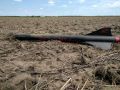 Landed in the Argonia dust.


Launches
Checklist
Pre-launch (before leaving town):
- Clean everything!
- Charge batteries: Raven LiPo, TeleGPS, TeleBT, old Mobius, pad camera, antenna camera, drill
- Clear memory in old Mobius, pad camera, antenna camera
- Check TeleGPS config and reset / clear memory
- Check Mobius config (correct video mode; sync clock), test and clear memory
- Test TeleGPS/TeleBT and leave transmitter battery unplugged
- Connect Raven battery (connect the two-pin plugs on the sled with pull-pin removed); check Raven config (set main pyro altitude to 900 feet); disconnect Raven battery
- Check contents of recovery pack
Pre-launch (night before launch):
- Assemble motor - remove delay charge
- Install motor in rocket
- Assemble ejection charges (1.5g Goex + wadding) x4
- Refold / repack parachute and rubberband
At the field:
- Connect Raven battery (connect two-pin plugs with pull-pin removed); verify that Raven lights up and 4 voltage beeps are heard
- IMPORTANT: disconnect Raven battery (disconnect two-pin plugs)
- Check terminal blocks for voltage
- Secure (4) ejection charges in charge wells with electrical tape and connect leads to terminal blocks
- Note the direction of the "ARM" label on the switchband to tell which end of the coupler is up. Insert the sled into the coupler from the bottom end. Rotate the sled to align the mark on the coupler with the mark on the bulkhead.
- Hold the coupler and aft bulkhead together and insert the pull-pin through the "ARM" hole in the switchband
- Visually check that the pull-pin is correctly inserted into the orange switch block inside the coupler
- Connect the two-pin plugs at the open end of the coupler. IMPORTANT: there should be no lights and no beeps. If there is any indication that the altimeter has powered up, disconnect the two-pin plugs immediately, disassemble, and check the wiring.
- Connect the forward bulkhead's three-pin plug with the plug in the open end of the coupler
- Align the forward bulkhead so the mark on the coupler is aligned with the mark on the bulkhead. Secure the forward bulkhead with 1/4" lock washers and hex nuts. Use a 7/16" nut driver to firmly tighten the nuts.
- Put a wrap of tape around the pull-pin and switchband to ensure that the pull-pin doesn't come out during the rest of the assembly.
- Attach the aft shock cord / nomex between aft airframe & coupler
- Pack drogue streamer & attach to aft shock cord
- Insert coupler into aft airframe with silver marks aligned; check / adjust friction fit
- Attach forward shock cord / nomex to coupler
- Thread forward shock cord through forward airframe and slide tube onto coupler with silver marks aligned; attach with plastic rivets
- Bundle forward shock cord w/masking tape
- Attach main parachute to forward shock cord
- IMPORTANT: if the parachute was pre-packed and has a rubber band, remove the rubber band
- Stow the parachute and forward shock cord in the upper airframe; it should slide in easily
- Connect TeleGPS battery and switch TeleBT on, check for comm & GPS lock
- Assemble nose cone with lock washer and eye nut
- Attach forward shock cord to nose cone
- Fit nose cone to upper airframe with silver marks aligned; install shear pins
- Verify that TeleGPS is still transmitting
- To RSO / pad with rocket, pad camera & recovery pack
At the pad:
- Place pad camera and start recording (short press of big button on top)
- Switch on-board camera on (short press of top button as rocket sits on pad, LED solid amber), REMOVE LENS CAP & start recording (short press of bottom button as rocket sits on pad, LED blinking amber)
- Rocket on rail
- Remove tape from pull-pin, and pull the pull-pin
- CHECK FOR PROPER NUMBER OF CHARGE CONTINUITY BEEPS [HI-HI-HI-HI]
- Apo-Main-Backup Apo-Backup Main...High=connected, low=disconnected
- Insert igniter into motor
- Check launch control leads for spark; connect leads to igniter
- Return to LCO
- Verify that TeleGPS still has GPS lock and is transmitting - if not, ask LCO to hold launch
- Go For Launch! Turn on the antenna camera and start recording
Recovery:
- Establish that TeleGPS is reporting a good landing position for the rocket
- Turn off antenna camera
- Return to the launch pad, retrieve the pad camera and turn it off
- Drive / walk to the rocket's landing position
- Immediately upon approaching the rocket, put the pull-pin back into the "ARM" hole in the switchband
- IMPORTANT: determine whether there are any unfired ejection charges in the charge wells, if so, double check that the altimeter is powered off (no beeping)
- Turn off the Mobius camera
- Gather everything up. It may be easiest to disconnect the parachute from the forward shock cord and put it into the recovery pack so the rest of the rocket can more easily be reassembled and carried in one piece
- If there are unfired ejection charges, they should be removed as soon as practical, either at the landing point, at the vehicle, or back in the prep area
- As soon as possible, open the nose cone and disconnect the battery from the TeleGPS
- Remove motor, remove the spent liner from the case and clean the case